
How to Choose the Right Electronic Pouring Sealants?
Electronic Pouring Sealants help protect circuit boards, sensors, connectors, and power modules from moisture, dust, vibration, and accidental contact. Yet the right material is not simply the hardest or most expensive one. A sealant poured around a compact control board must flow into narrow gaps without trapping air. It must also cure reliably around components that may be sensitive to heat or chemical exposure. Small choices matter. An overly viscous formula can leave hidden voids; a rigid cured layer may stress solder joints during temperature changes. These risks are easy to overlook on a product sheet.
A sound selection starts with real operating conditions: expected temperature range, humidity, vibration, insulation needs, and service life. Compare silicone, polyurethane, and epoxy options by viscosity, cure method, adhesion, hardness, thermal performance, and repairability. Check compatibility with the board, wire insulation, plastics, and metals, rather than relying on a general label such as “electronics grade.” Manufacturer technical data sheets provide useful limits, but they cannot predict every assembly detail. A small trial pour can reveal bubbles, poor wetting, cure inhibition, or difficult rework before production begins. Keep process records. Even careful testing has limits, and one overlooked coating or residue can change the result. This guide explains how to weigh these factors and choose a sealant suited to both the device and the manufacturing process.
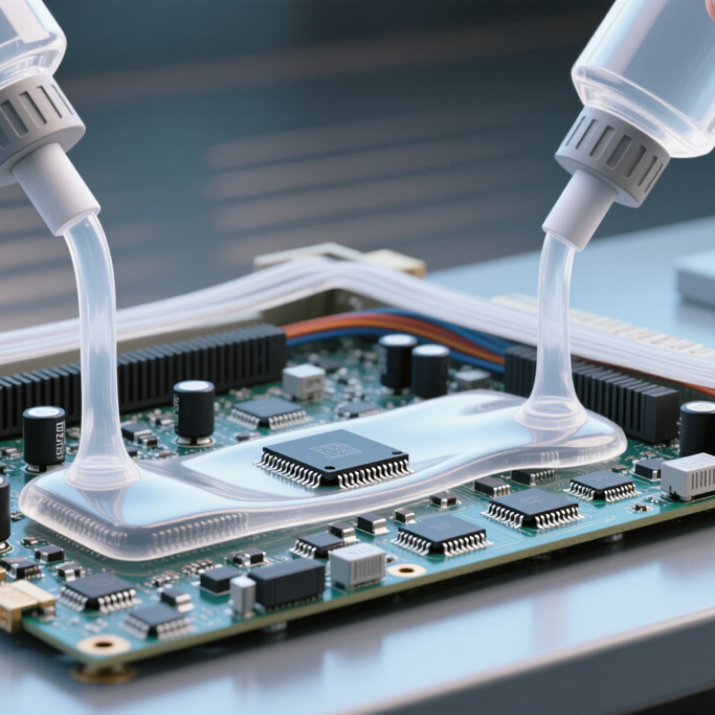
Define Electrical, Thermal, and Chemical Requirements Before Choosing a Sealant
How to Choose the Right Electronic Pouring Sealants?
Define Electrical, Thermal, and Chemical Requirements Before Choosing a Sealant
Before choosing an electronic pouring sealant, define the electrical conditions it must handle. Record working voltage, expected insulation resistance, and whether the assembly faces moisture or electrical noise. Check the sealant’s technical data for dielectric properties and confirm they suit the design. A high rating alone does not guarantee a reliable result. Small details matter.
Thermal demands deserve equal attention. Note the device’s operating temperature, heat spikes, and repeated heating and cooling. A rigid material may stress solder joints or components as temperatures change. Check cure conditions, too, especially if the assembly contains heat-sensitive parts. Chemical compatibility can be less obvious. List nearby plastics, metals, cleaning fluids, oils, and coatings, then confirm the sealant will not damage them. It is easy to overlook a residue from cleaning. Test a representative assembly when possible, since a data sheet cannot reflect every real-world combination.
Tips: Keep a short requirements sheet with voltage, temperature range, and chemical exposures. Pour a small sample around actual components, then inspect for trapped air, poor adhesion, or cure problems. If results look uncertain, pause and review the material choice before production.
| Sealant chemistry | Typical dielectric strength | Typical thermal conductivity | Typical service temperature | Electrical considerations | Thermal considerations | Chemical and environmental resistance | Often suitable for | Key limitations to check |
|---|---|---|---|---|---|---|---|---|
| Epoxy | About 15–30 kV/mm | About 0.2–0.8 W/(m·K) for unfilled grades; higher for thermally filled grades | Often about −40 to 150°C, depending on formulation | Generally offers strong insulation and good dimensional stability. Confirm dielectric strength, volume resistivity, and insulation requirements after cure. | Rigid formulations can transfer heat effectively when filled, but usually accommodate thermal expansion and vibration less readily than elastomers. | Often good resistance to moisture, oils, and many solvents; resistance depends on the specific chemical and exposure conditions. | Rigid encapsulation of sensors, transformers, power components, and assemblies needing strong mechanical protection. | Can be difficult to remove or rework. Cure exotherm, shrinkage, and stress on delicate components should be evaluated. |
| Silicone | About 15–25 kV/mm | About 0.2–0.8 W/(m·K) for common unfilled grades; thermally filled grades can be higher | Often about −50 to 200°C, depending on formulation | Typically provides good electrical insulation across a wide temperature range. Check dielectric properties at the intended temperature and humidity. | Flexible materials can accommodate thermal cycling and vibration. A thermally conductive grade may be needed for heat-sensitive components. | Good weathering, ozone, and moisture resistance; compatibility with oils, fuels, and solvents varies by formulation. | Assemblies exposed to temperature cycling, vibration, outdoor conditions, or components that need compliant encapsulation. | Softness may provide less structural support. Silicone contamination can affect bonding, coating, or other downstream processes. |
| Polyurethane | About 15–25 kV/mm | About 0.2–0.6 W/(m·K) for many unfilled grades | Often about −40 to 120°C, depending on formulation | Can provide good insulation and flexible protection. Verify electrical performance after exposure to moisture and temperature. | Its flexibility can reduce stress on components; standard grades are not necessarily high-thermal-conductivity materials. | Resistance to water, oils, and chemicals varies considerably. Some formulations can be sensitive to moisture during processing or long-term exposure. | Encapsulation where flexibility, impact protection, and moderate operating temperatures are important. | Check humidity sensitivity during mixing and cure, hydrolysis resistance, and compatibility with the actual fluids or cleaning agents. |
| Thermally conductive silicone | Often about 10–20 kV/mm; confirm the grade and test method | Commonly about 0.8–3 W/(m·K), with specialty grades available outside this range | Often about −40 to 180°C, depending on formulation | Thermal fillers can change electrical properties. Confirm that the selected grade is electrically insulating if that is required. | Designed to improve heat transfer while retaining silicone flexibility. Compare conductivity alongside viscosity and cured hardness. | Generally retains silicone-like weathering and moisture performance, but chemical compatibility remains formulation-specific. | Power electronics, LED assemblies, and components where heat transfer and thermal-cycle compliance are both priorities. | Higher filler loading can affect flow, dispensing, and component wetting. Thermal conductivity alone does not guarantee a low-resistance heat path. |
| Acrylic | About 10–25 kV/mm, depending on formulation and cure | About 0.15–0.4 W/(m·K) for many unfilled grades | Often about −40 to 120°C, depending on formulation | Electrical properties and cure depth should be validated for the actual part geometry and light exposure, where UV curing is used. | Usually selected for rapid curing or rework considerations rather than high heat transfer. | Resistance to moisture and chemicals varies by chemistry; test against the specific cleaner, solvent, or process fluid. | Small assemblies and applications where fast cure or easier inspection and repair are useful. | Shadowed areas may not cure fully in light-cured systems. Confirm cure method, depth, and compatibility with plastics. |
| Selection note: Values shown are indicative ranges for common material families, not guaranteed specifications. Actual properties vary by formulation, filler loading, cure schedule, specimen thickness, and test method. Before selection, define the required dielectric performance, operating and peak temperatures, heat-flow path, chemical exposure, moisture level, component sensitivity, and rework needs; then verify the supplier’s current technical data and test the material in the finished assembly. | ||||||||


