
How to Choose a Centrifugal Degasser?
Choosing a Centrifugal Degasser is not a matter of picking the largest unit in a catalog. The right choice depends on the liquid, incoming gas load, required flow rate, and conditions at the installation site. A unit that performs well in a clean-water test may behave differently with foaming fluids, changing temperatures, or uneven feed. Small details matter. Look closely at wetted materials, seal design, motor rating, access for cleaning, and the supplier’s stated operating limits.
A useful selection principle is: “Match the degasser to the gas load and flow you actually expect—not just the headline capacity.” This is an original editorial statement, not a verified quotation from a named industry expert. No source was provided to confirm an expert’s name or exact words, so attributing it would risk misleading readers. Before purchase, ask for performance data under conditions close to your own process. Check how efficiency is measured, what maintenance intervals are recommended, and which parts require routine replacement. Ask about start-up support, spare-part availability, and what happens when feed conditions fluctuate.
Numbers help. So does field experience. Yet supplier claims still need scrutiny. A practical comparison should include total operating cost, not only purchase price. That means power use, maintenance, downtime, and operator workload. The choice may remain imperfect; actual performance can vary after installation. A careful trial, with clear acceptance criteria, can expose that gap before it becomes an expensive surprise.
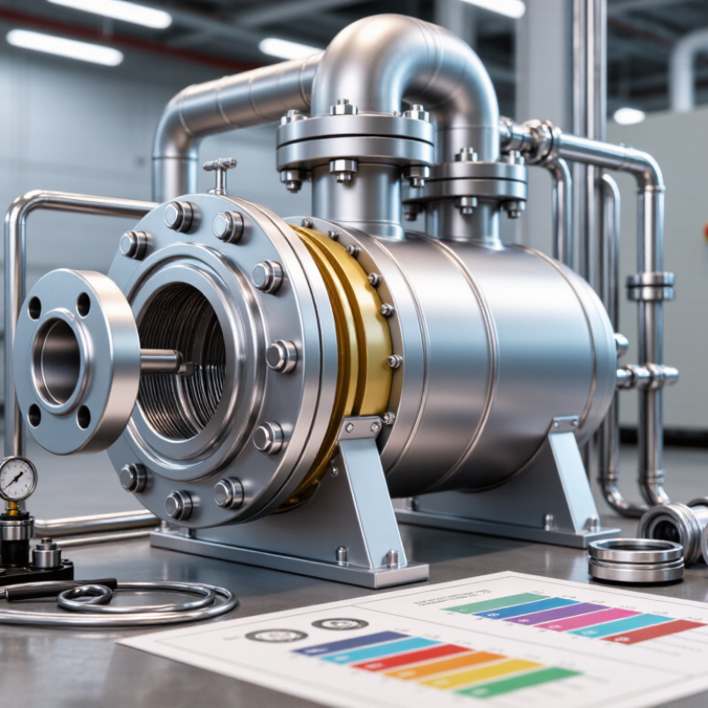
Define the Gas-Removal Duty and Operating Conditions
Before comparing centrifugal degassers, define the gas-removal duty. Is the target entrained air, foam, or dissolved gas? These require different treatment, and a centrifugal unit may not remove each equally well. A sample can look clear while fine bubbles remain after a pump or mixer. Record the liquid flow rate, estimated gas fraction, and required outlet condition. Use measured values where possible. Small bubbles matter.
Describe the operating window, not just the average. Note minimum and maximum flow, pressure, temperature, viscosity, and changes in liquid composition. Solids or sticky residues can affect separation and cleaning needs. A warm, low-viscosity liquid may behave differently from a cold batch. Include foaming tendencies and any brief flow surges; these details are easy to miss in a tidy process sheet.
Then match the duty to the equipment’s usable range. Ask what performance is expected at peak flow, and under which test conditions. Check available space, connections, drain access, and how operators will verify performance during startup. A rotor-speed figure alone is not enough. I would be cautious about sizing from one convenient sample: it can hide real variation. A short trial using representative liquid may expose gaps in the assumptions.
Compare Centrifugal Degasser Designs and Separation Principles
A centrifugal degasser uses rotation to separate gas from liquid by density. As the mixture spins, denser liquid moves outward, while gas gathers closer to the rotor’s center and exits through a vent. The exact path depends on the design. Tangential-feed chambers create a swirling flow; other rotors guide liquid through defined channels to control contact time and reduce carryover.
Compare designs by how they manage feed, residence time, and gas discharge—not by rated capacity alone. A compact, single-stage unit may suit steady flows with modest gas loads. A multi-zone rotor can provide more controlled separation when flow or gas content varies, but it may add cleaning and maintenance needs. Real fluids behave less neatly. Foam, changing viscosity, and fine bubbles can weaken separation, even when a unit meets its published flow rate.
It is tempting to compare only throughput, but that can mislead. Check the expected gas fraction, operating pressure, liquid properties, and acceptable residual gas. Ask how the rotor handles surges and whether operators can inspect wear surfaces without lengthy disassembly. A clear test using the actual process fluid is more useful than a smooth brochure curve. Note one limitation: centrifugal force can remove entrained or free gas, but dissolved gas may need a different treatment approach.
| Design or configuration | Separation principle | Best suited to | Advantages | Limitations and selection considerations |
|---|---|---|---|---|
| Single-stage centrifugal degasser | A rotating element creates a centrifugal field. The denser liquid is driven outward while lower-density gas moves toward the lower-pressure central region, where it can separate and be vented. | Continuous processing where the incoming liquid contains free or entrained gas and a compact mechanical separator is desired. | Continuous operation; compact footprint; separation can be rapid when the feed and operating conditions are suitable. | Performance depends on rotational speed, flow rate, liquid properties, and gas loading. It may not remove dissolved gas effectively without an additional mass-transfer step. |
| Multi-stage centrifugal configuration | Liquid passes through successive separation stages. Each stage provides another opportunity for gas bubbles to migrate away from the liquid under centrifugal acceleration. | Applications requiring additional gas removal or more controlled separation than a single stage can provide. | Can improve overall separation by repeating the gas-removal process; may handle changing gas loads more effectively than a single stage when properly designed. | More components and controls can increase equipment complexity, maintenance needs, and pressure loss. The actual benefit depends on the feed and stage design. |
| Vacuum-assisted centrifugal degasser | Centrifugal action separates free gas from the liquid, while reduced pressure encourages dissolved or finely dispersed gas to leave the liquid. A vacuum system removes the released gas. | Liquids requiring deeper degassing than mechanical centrifugal separation alone can typically achieve. | Combines density-based separation with lower-pressure gas release; can address both entrained gas and some dissolved gas, depending on the liquid and process conditions. | Requires vacuum equipment and control of air ingress. Vacuum level, temperature, residence time, and liquid volatility affect performance; foaming may require attention. |
| Inline centrifugal gas–liquid separator | A swirling or rotating flow creates a radial density gradient. Gas collects toward the core of the flow while liquid moves toward the outer region; separate outlets route the phases away. | Continuous pipelines or process lines where a vessel-based batch step is undesirable and the flow can be kept within the separator’s operating range. | Can be integrated directly into a process line and may require less floor space than a large separation vessel. | Separation is sensitive to flow rate, flow regime, pressure, and gas fraction. It generally separates free gas rather than removing gas that remains dissolved in the liquid. |
| Centrifugal degasser with upstream conditioning | Feed conditioning first promotes bubble formation or coalescence; centrifugal force then helps separate the resulting gas bubbles from the liquid. | Feeds with fine bubbles, variable gas content, or properties that make direct separation difficult. | Conditioning can make bubbles easier to separate and may improve process stability when matched to the liquid and operating conditions. | Additional conditioning equipment can add cost and maintenance. The selected method must be compatible with the liquid and should not create unwanted emulsions, foam, or contamination. |
| Selection checklist | Define whether the target is free gas, entrained bubbles, or dissolved gas. Then compare required outlet gas content, liquid flow and pressure, viscosity, temperature, foaming tendency, available utilities, maintenance access, and allowable pressure loss. Request performance data for the actual process conditions and confirm how the stated result is measured. | |||
| Note: Equipment terminology and internal geometry vary by application and supplier. Centrifugal separation is primarily driven by phase-density differences; dissolved-gas removal may require vacuum, heating, or another mass-transfer method. | ||||
Size the Unit for Flow Rate, Pressure, and Required Gas Removal
A centrifugal degasser should be sized around the liquid flow it must handle, not just the pipe diameter. Start with normal, minimum, and peak flow rates. Record them during real operating conditions if possible. A short flow spike can reduce separation time and let gas carry over. Do not size only for the average.
Pressure matters. Confirm both inlet and outlet pressures, plus the unit’s allowable pressure drop and pressure rating. Higher pressure may keep some gas in solution, while a pressure change can release it. The details depend on the liquid and process. Flow basis matters.
Next, define the gas-removal target. Distinguish entrained bubbles from dissolved gas; a centrifugal unit may not remove both equally well. Estimate the incoming gas load, and note liquid temperature, viscosity, and gas composition. These affect separation performance. Ask for performance data at conditions close to yours, not just a headline removal figure.
Sizing data is rarely perfect. Plant measurements may miss brief surges or changing gas loads, so document assumptions and leave room for operating variation. During commissioning, compare inlet and outlet gas levels at several flow rates. If the target is missed, check for carryover, unstable flow, or an unrealistic removal requirement before changing the unit size.
How to Choose a Centrifugal Degasser?
Size the unit against the process flow rate, operating pressure, and required gas removal. The chart shows illustrative design cases—not measured equipment performance or guaranteed capacity.
Use these values as example process inputs only. Confirm the selected unit’s capacity and gas-removal performance at the actual liquid properties, pressure, temperature, and gas load.
Select Materials, Seals, and Control Features for the Process
How to Choose a Centrifugal Degasser?
Select Materials, Seals, and Control Features for the Process
Start with the liquid, not the equipment catalogue. Record its chemistry, temperature, solids, and cleaning-cycle conditions. NACE International’s IMPACT study estimated corrosion costs at US$2.5 trillion worldwide, or 3.4% of global GDP, and found that better corrosion management could save 15–35%. Those figures make material selection more than a purchase detail. Match wetted parts to the actual fluid: a stainless-steel grade may suit a mild stream but fail in chloride-rich service. Check the full operating range, not just normal production. Still, no alloy is universally safe.
Seals need the same process-specific review. Confirm pressure, temperature, gas content, and whether brief dry-running is possible during startup. Ask how the seal arrangement handles leakage and maintenance access. API Standard 682 provides a useful framework for mechanical seals in centrifugal pumps, though the final configuration should reflect the degasser’s duty and site procedures. Small details matter. A seal plan that looks adequate on paper may be awkward beside a hot, crowded skid.
For controls, specify measurable operating limits: inlet pressure, outlet gas content, vibration, and liquid flow. Variable-speed control can help match changing throughput, but avoid assuming it always saves energy. The U.S. Department of Energy’s pumping-system sourcebook reports that pumping systems can consume 25–50% of energy in some industrial facilities. Use alarms and trends to identify drift before product quality suffers. A simple sensor can be wrong, too; verify readings during commissioning.
Assess Installation Needs, Maintenance, and Performance Data
How to Choose a Centrifugal Degasser?
Assess Installation Needs, Maintenance, and Performance Data
Start with the actual installation, not the catalogue rating. Measure available floor space, headroom, inlet and outlet elevations, and clearance for lifting the rotor. Confirm the expected flow range, fluid temperature, viscosity, solids load, and gas content. A unit that fits the pipework may still be difficult to service. Check utility requirements, drainage, ventilation, and access to seals and bearings. Fit matters. The U.S. Department of Energy’s Improving Pumping System Performance sourcebook notes that pumping systems use nearly 20% of global electricity demand; this is broad context, not a degasser efficiency benchmark. Compare motor power and operating conditions at the site, rather than treating that figure as a product rating.
Ask for performance data at your own process conditions. Request throughput, gas-removal efficiency, pressure drop, power draw, and operating limits, with test methods and fluid properties stated. Compare results at both normal and peak flow. A single best-case figure can mislead. For maintenance planning, ask how often seals, bearings, and wear components need inspection, and whether routine work requires special lifting tools. Review service records and vibration or temperature trends from similar installations where available. These details can expose a mismatch before commissioning. Still, reported field data may be incomplete; record a baseline during acceptance testing, then compare it with operating readings over time.


