
What Are the Top MPO Cable Types in 2026?
Data-center links are moving toward higher speeds, denser fiber paths, and tighter installation windows. The Ethernet Alliance’s 2024 Ethernet Roadmap tracks the industry’s progression through 400GbE and 800GbE, with work toward 1.6TbE. That evolution makes MPO Cable selection more than a connector decision: fiber count, polarity, fiber mode, and transceiver compatibility all matter.
Industry reports offer useful context, but they do not replace a port-by-port design review. Uptime Institute’s 2024 Global Data Center Survey describes power and capacity constraints facing operators. Those pressures can make rack space and cable routing especially important. LightCounting’s optical-transceiver market analysis also follows the shift toward faster data-center optics. Still, neither report tells a buyer whether an MPO-12 trunk or MPO-16 assembly will fit a particular deployment. Check the equipment documentation.
This guide compares common MPO cable types, including multimode and single-mode assemblies, trunk cables, and breakout harnesses. It also explains connector pinning, polarity, and end-face choices, which are easy to overlook on a busy installation day. MPO-12 remains widely used, while MPO-16 can support interfaces designed for 16 fibers; neither is universally best. Small details matter. A polished connector, matching transceiver, and verified polarity can prevent costly rework. The awkward truth is that catalog labels sometimes hide meaningful differences. Treat compatibility claims as a starting point, then verify them against the link design and applicable standards.
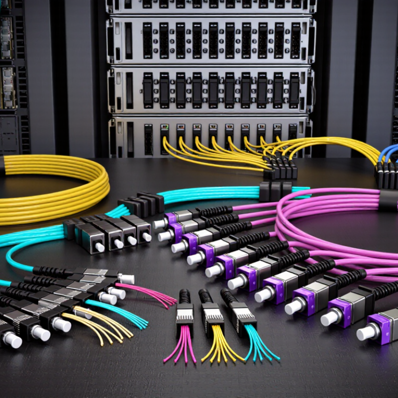
How MPO Cables Are Classified by Fiber Count and Fiber Mode
MPO cables are classified by both fiber count and fiber mode. The count describes the fibers inside the cable, not always the number carrying traffic. MPO-12, MPO-16, MPO-24, and MPO-32 assemblies are common options. Yet an MPO-12 link may use only eight fibers, leaving four positions dark. That matters.
IEEE 802.3cm specifies 400GBASE-SR8 with 16 fibers: eight transmit and eight receive. Its 400GBASE-SR4.2 specification uses eight fibers. These examples show why port speed alone cannot determine the right MPO count. The Ethernet Alliance’s 2024 Ethernet Roadmap tracks 400GbE and 800GbE technologies, reinforcing the need to check each transceiver’s fiber map before ordering. Small mismatches can leave a link unusable.
Mode is a separate choice. Multimode OM4 or OM5 is commonly used for short-reach links inside data centers; single-mode OS2 supports longer-reach applications. IEEE 802.3cm specifies up to 100 meters for 400GBASE-SR8 over OM4. A cable’s mode, connector polarity, and active-fiber layout must all match the optics. The label alone can mislead. Even experienced teams sometimes focus on fiber count and overlook polarity, so verify the complete link design against the applicable IEEE specification.
What Are the Top MPO Cable Types in 2026? – How MPO Cables Are Classified by Fiber Count and Fiber Mode
MPO cables are commonly specified by the number of fibers in the assembly and by fiber mode. The counts below describe cable or connector configurations; high-count trunks may use multiple MPO connectors rather than one large ferrule.
| Fiber count | Typical MPO configuration | Fiber mode options | Common use | Selection notes |
|---|---|---|---|---|
| 8 fibers | MPO-8 or an 8-fiber array within a larger-format assembly | OS2 single-mode; OM3 or OM4 multimode | Parallel-optics links using four transmit and four receive fibers, where supported by the transceiver | Confirm the transceiver’s fiber count and polarity; some 8-fiber links use a 12-fiber MPO interface with unused positions. |
| 12 fibers | MPO-12, typically one row of 12 positions across two rows | OS2; OM3; OM4; OM5 | Common backbone and data-center links; frequently used in legacy parallel multimode deployments | A 12-fiber connector can serve an 8-fiber application, leaving some positions unused. Check the pinning and polarity scheme. |
| 16 fibers | MPO-16, commonly arranged as two rows of eight | OS2; OM4; OM5 | Higher-density parallel links, including applications designed for 16-fiber transceiver interfaces | Match the connector format to the equipment; MPO-16 is not interchangeable with MPO-12 without compatible hardware. |
| 24 fibers | MPO-24, commonly two rows of 12 | OS2; OM3; OM4; OM5 | High-density trunk cabling and structured cabling between panels, cassettes, and equipment | Useful where more fibers are needed per connector. Verify cassette compatibility and the required breakout arrangement. |
| 32 fibers | MPO-32, commonly two rows of 16 | OS2; OM4; OM5 | High-density parallel-optics connections and trunk architectures requiring 32 positions | Confirm that ports, adapters, and patching components support the same MPO position count. |
| 48 fibers | MPO-48 or a trunk built from multiple MPO arrays | OS2; OM4; OM5 | Backbone trunks and high-density connections between distribution points | The total cable count may be distributed over multiple connectors; check the assembly drawing rather than assuming one ferrule. |
| 64 fibers | MPO-64 or a multi-array trunk configuration | OS2; OM4; OM5 | High-capacity data-center backbone cabling and modular cross-connect systems | Specify total fiber count, connector count, breakout layout, and polarity at both ends. |
| 72 or 96 fibers | Usually a multi-array MPO trunk rather than a single standard MPO ferrule | OS2; OM4; OM5 | Large-capacity backbone links and pre-terminated modular cabling | Document the number and type of MPO connectors, plus the mapping between ends, for correct installation and testing. |
| 144 fibers | Typically a trunk cable containing multiple MPO connectors or breakout branches | OS2; OM4; OM5 | Very high-density backbone cabling in data centers and enterprise networks | Treat 144 as the cable’s total fiber count, not necessarily the fiber count of one MPO connector. Confirm routing, labeling, and test records. |
Fiber-mode guide: OS2 is single-mode fiber. OM3, OM4, and OM5 are multimode fiber grades; OM4 and OM5 are common choices for newer multimode links, while OM3 may remain in existing installations. Fiber mode, connector format, polarity, and transceiver requirements must all match end to end.


