Why Does Printed Circuit Board Quality Matter?
A printed circuit board is more than a flat surface holding electronic parts. It is the structure that connects them, controls electrical paths, and helps a product operate reliably. A tiny defect can matter: a lifted copper trace, a poorly plated via, or solder bridging two pads may cause intermittent faults. Some problems appear only after heat, vibration, or repeated use. Others hide beneath components, beyond the reach of a quick visual check.
That is why board quality affects performance, safety, production cost, and product life. Henry Ott, an electromagnetic compatibility engineer and author, expressed a useful design principle: “The best way to solve EMC problems is to not create them in the first place.” His point applies to PCB quality, too. Careful material selection, sound layout, controlled fabrication, and suitable testing can prevent problems before assembly. These steps do not make every failure impossible. They make defects less likely and easier to trace.
Quality is not one inspection result. It is a chain of decisions. A clean-looking board may still have weak internal plating or inconsistent impedance. Conversely, a small cosmetic mark may not affect function. Context matters. Manufacturers and designers should define acceptance criteria, review process controls, and match testing to the board’s real operating conditions. This introduction explores why printed circuit board quality matters, what can undermine it, and how dependable design and manufacturing practices protect the finished product. There are trade-offs, too: tighter controls may raise upfront costs. Ignoring them can cost more later.
What Printed Circuit Board Quality Encompasses
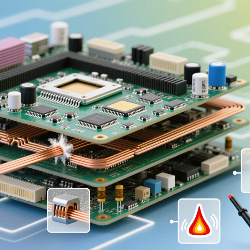
Printed circuit board quality is more than a clean surface or precise outline. It includes the materials, dimensions, copper features, holes, and protective coatings that determine how a board performs. The details matter.
A useful assessment starts with the substrate. Its thickness, thermal behavior, and stability should suit the board’s operating conditions. Copper traces must match the design in width and spacing, while plated holes and vias need reliable connections between layers. Under magnification, uneven plating or exposed copper can signal trouble. Not always, though; inspection findings need context.
Quality also encompasses solder-mask coverage, component-pad accuracy, and board flatness. A mask that shifts over a pad can complicate assembly, while a warped board may not sit evenly in a fixture. Electrical tests can check for opens and shorts, but they do not reveal every weakness. Some defects emerge only after heat, vibration, or repeated use. That is easy to overlook.
Good documentation ties these checks to clear acceptance criteria, inspection records, and test results. Requirements should reflect the product’s real demands, not simply aim for the tightest tolerances. A basic sensor board and a high-current control board face different risks. Even experienced teams sometimes discover that a specification missed a practical assembly issue.
How PCB Quality Affects Electrical Performance
PCB quality directly shapes resistance, signal integrity, and heat. A trace that is thinner or narrower than specified carries less current efficiently. NIST reference data give copper’s resistivity as about 1.68 × 10⁻⁸ Ω·m at 20°C. For an ideal 100 mm trace, 0.2 mm wide and 35 μm thick, that means roughly 0.24 Ω resistance. At one ampere, the trace would drop about 0.24 volts and dissipate 0.24 watts. Small differences matter. Etching variation, thin plating, or a rough copper surface can push real performance away from that estimate.
High-speed signals add another constraint. Variations in dielectric thickness and material properties change impedance, while copper roughness can increase signal loss as frequency rises. IPC-2152 provides guidance for sizing conductors against current and temperature rise, but calculations still depend on the board’s actual stack-up and cooling. A clean-looking board is not proof of consistent electrical quality. I would check trace dimensions, copper weight, and dielectric data against the design, then verify critical nets with measurements. The estimate is useful, not a guarantee.
Why Does Printed Circuit Board Quality Matter? - How PCB Quality Affects Electrical Performance
| PCB quality dimension | What is controlled or inspected | Electrical performance impact | Why it matters in practice |
|---|---|---|---|
| Trace width and spacing | Etched copper geometry is checked against the design and applicable manufacturing tolerances. | Trace width affects resistance; spacing affects coupling and the risk of unintended shorts. | Consistent geometry helps maintain predictable current capacity, signal behavior, and clearance. |
| Copper thickness | Finished copper thickness is verified against the board specification. A nominal 1 oz/ft² copper layer is about 35 µm before process-related variation. | Thicker copper generally lowers trace resistance and can reduce resistive heating for a given current. | The specified thickness must be considered in current, temperature-rise, and impedance calculations. |
| Dielectric thickness and properties | Layer spacing, dielectric constant, and loss characteristics are controlled for the selected laminate and stack-up. | These properties influence characteristic impedance, capacitance, propagation delay, and dielectric loss. | Stack-up variation can shift impedance and timing, particularly on high-speed or high-frequency nets. |
| Layer registration | Alignment of copper layers, drilled holes, and pads is inspected during fabrication. | Misregistration can reduce clearances, weaken connections, or cause unintended coupling between layers. | Accurate alignment supports reliable routing, isolation, and via-to-pad connections. |
| Via and plated-hole quality | Hole size, copper plating continuity, and connection to the intended copper layers are checked. | Defective plating or connections can increase resistance or create intermittent and open circuits. | Reliable vias are essential for layer transitions, power distribution, and signal continuity. |
| Copper surface roughness | Copper foil and surface profile are selected and controlled for the design requirements. | At higher frequencies, surface roughness can increase conductor loss because current is concentrated near the conductor surface. | It becomes more important for low-loss, high-speed, and RF designs than for many low-frequency circuits. |
| Cleanliness and insulation | The board is inspected for conductive residues, contamination, and insulation defects. | Contamination can reduce insulation resistance and contribute to leakage current or electrochemical migration. | Clean surfaces and adequate spacing help preserve electrical isolation, especially in humid or high-voltage environments. |
| Impedance verification | For controlled-impedance designs, test coupons or other agreed methods are used to check the fabricated stack-up. | Impedance deviations can cause reflections and signal-integrity problems on transmission lines. | Verification helps confirm that material properties and fabricated geometry meet the design target. |
Electrical results depend on the complete design, materials, operating conditions, and fabrication tolerances; acceptance limits should be defined in the board specification.
Why Material and Build Quality Shape Reliability
Why Does Printed Circuit Board Quality Matter?
Why Material and Build Quality Shape Reliability
A board can pass an initial power-up and still fail after months of heat cycling. Material choice helps determine how well it handles temperature, moisture, and electrical stress. For example, a laminate with poor thermal stability can expand unevenly, stressing plated-through holes and solder joints. A thin copper barrel may crack after repeated temperature swings. These failures often begin where inspection is hardest: inside the board. IPC-9701A defines thermal-cycling tests for evaluating surface-mount solder attachment, with cycles to electrical failure recorded as a reliability measure. It is a useful reminder that one successful bench test is not enough.
Build quality matters just as much. Accurate drilling, clean copper surfaces, and consistent plating support dependable connections between layers. Small variations can become open circuits under vibration or heat. I have seen a board look pristine while a hidden via defect explains intermittent resets; appearance is not proof.
Tips: Ask for laminate specifications, copper-weight details, and process inspection records. For critical designs, request thermal-cycling evidence tied to the actual assembly. Check the failure criteria, too. A report without test conditions tells only half the story. Conversely, demanding the toughest material everywhere can raise cost without improving the real failure risks. The right choice depends on operating temperature, current, and expected service life.
Why Does Printed Circuit Board Quality Matter?
Typical glass-transition temperature (Tg) ranges illustrate how laminate choice can affect a PCB’s resistance to heat during assembly and operation.
Bars show the midpoint of representative ranges: standard FR-4, 130–140°C; high-Tg FR-4, 170–180°C; and polyimide, 250–260°C. Actual values vary by formulation and supplier. A higher Tg can help a laminate withstand heat, but overall PCB reliability also depends on factors such as copper adhesion, thermal expansion, moisture resistance, and manufacturing quality.
How PCB Defects Affect Safety and Product Lifespan
A tiny defect can have an outsized effect. A hairline crack in a copper trace may interrupt power after repeated heating and cooling. Solder voids, residue, or delamination can also create unstable connections, unwanted current paths, or heat buildup. These problems may begin as intermittent resets, then become permanent failures. In a medical monitor or vehicle control unit, an unexpected failure can affect safety, not just convenience.
The NFPA’s Home Electrical Fires report estimates 24,200 U.S. home structure fires annually involved electrical failure or malfunction from 2015 to 2019, with 295 deaths and $1.2 billion in direct property damage.
This is not a PCB-specific figure, but it shows the stakes of electrical reliability. For board workmanship, IPC-A-600 defines visual acceptance criteria for printed boards; inspection against a standard helps catch flaws before assembly.
Still, inspection is not magic. A board can pass visual checks and fail later under vibration, moisture, or thermal cycling. Engineers should pair inspection with electrical testing and choose materials suited to the product’s actual environment. Small savings on testing can become costly repairs, shortened service life, or a safety risk. I would not treat one clean sample as proof of lasting quality.
How PCB Quality Is Tested and Controlled
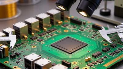
PCB quality is checked at several stages, not only after assembly. Incoming inspection can reveal warped panels, damaged copper, or inconsistent board thickness. Automated optical inspection compares copper patterns with design data and flags missing traces or shorts. Electrical tests then check continuity and isolation. A board may look clean and still fail electrically. That is why visual review alone is not enough.
Testing should match the board’s design and working conditions. Cross-sections can expose thin copper or poor plating inside a hole. Thermal cycling can show whether repeated temperature changes stress the board. These tests do not replace process control: operators also track material batches, machine settings, and inspection results. Measurement equipment needs regular calibration. Sampling plans matter, too; testing a few boards cannot reveal every defect. In practice, a well-documented process is more useful than a single impressive test result. It is easy to miss details when production gets busy.
Tips: Keep test records linked to each production lot. Review recurring defects, even when they seem minor. A slightly misaligned hole may not cause an immediate failure, but it deserves investigation. Some inspection methods also have limits, so teams should question what a test cannot detect.